The stereo 3D pendulum simulation realizes spherical pendulum motion under different conditions. The simplest case is when no external forces are acting. The motion is determined only by the constraint of pendulum’s massless bar (string). The second option is to introduce an external force (force of weight or gravity force), which is a conservative force and creates a conservative force field. Additionally, the observer may introduce non-conservative forces such as dissipative force of friction and external periodical sinusoidal forces.
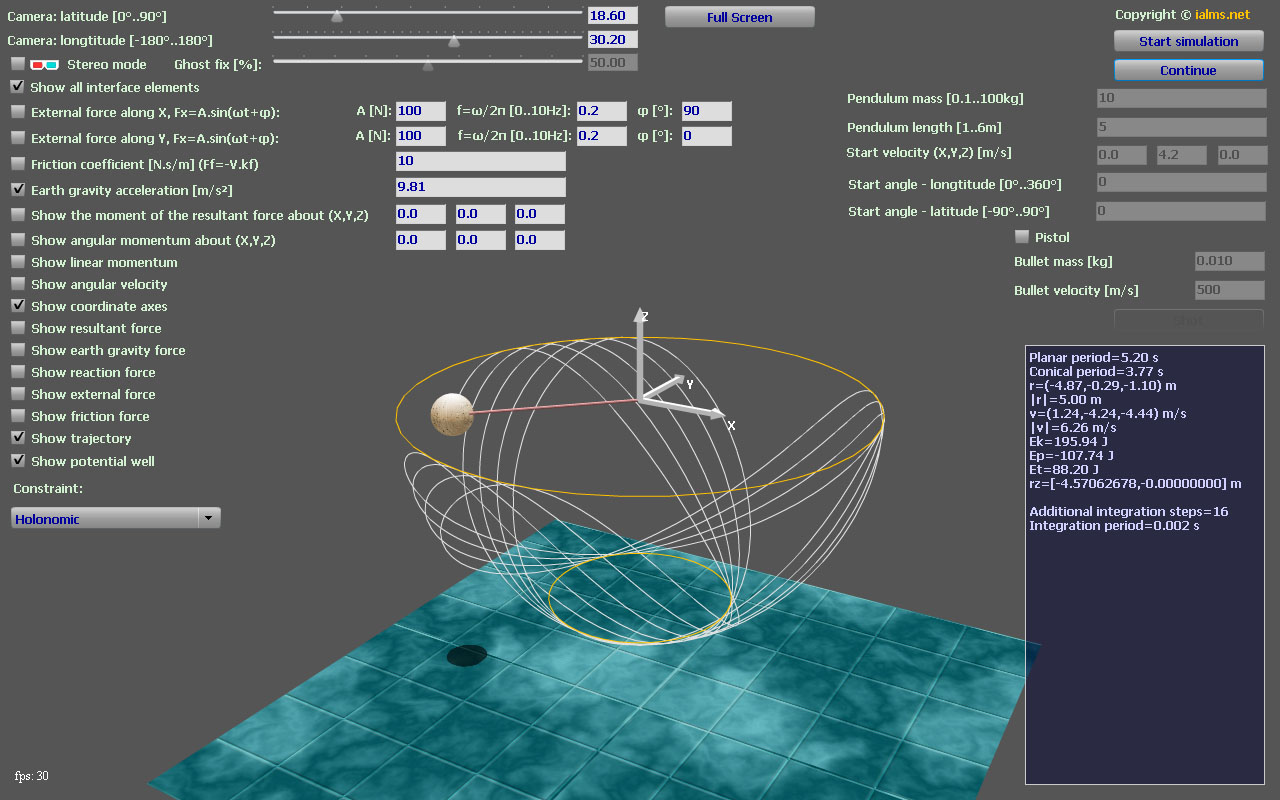
Figure 1. The presented simulation of spherical pendulum.
To start the simulation the user needs to click the ‘Start simulation’ button. ‘Pause’ button pauses the simulation, but in ‘Pause’ mode the viewer may still rotate the camera and toggle the display of vectors and other elements. The pendulum is visualized in 3D graphics with textures, light shades and anti-aliasing to increase the ease of perception. All vectors are presented in 3D view as arrows with different colours. The space reference frame axes can be observed by checking the ‘Show coordinate axes’ checkbox (see Figure 1). Space reference frame basis is visualized with vector arrows in white colour. Students may display the momentum of the pendulum as a vector (purple colour). Further, all acting forces can be shown with differently coloured vectors, along with angular momentum vector (magenta colour) and moment of the resultant force vector (green colour). All these vectors are visualized by checking the corresponding checkboxes (Figure 1). The two moments are calculated towards an origin point (default is 0,0,0), which is selected in the corresponding fields as X, Y and Z coordinates. In the data panel (lower-right of the interface), values of the presented vectors are printed along with other scalar quantities related to the simulated process such as period of the pendulum, pendulum energies and the potential well. At any moment the user may hide excessive controls on the screen by unchecking the ’Show all interface elements’ checkbox. To control camera view, the observer should manipulate the sliders at the top of the interface, which control camera latitude and longitude. Before starting the simulation, the student may enter initial values for pendulum position through two angles named latitude and longitude (see ‘Start angle’ fields). Before clicking the ‘Start’ button, starting linear velocity of the pendulum may be set using ‘Start velocity’ fields. Learners may also select the pendulum length and mass in the corresponding fields. At any time the user may show or hide pendulum’s trajectory and its potential well by checking or unchecking the corresponding checkboxes.

Figure 2. Anaglyph stereoscopic 3D glasses. Left: red-cyan plastic frame glasses; center top: red-cyan paper frame glasses; right: green-purple plastic frame glasses.
At any moment, the student may switch the simulation into 3D-stereoscopic view mode by checking the 'Stereo mode' checkbox. Thus users may observe the process using red-cyan 3D-stereoscopic anaglyph glasses (see Figure 2 above).
You may maximize your browser window to enlarge the simulation or you may use the 'Full screen' button. In full screen mode you may not edit the simulation text fields. You need to switch back to normal view mode to edit these fields by clicking the 'Esc' key on your keyboard.
|
Disclaimer: This website (ialms.net) does not guarantee the accuracy of any of it's content. Use this site and its content at your own risk. Note: This website (ialms.net) does not use cookies. Copyright © www.ialms.net |